A GPS-based clock and timer circuit built with an Arduino Uno and NEO-6M GPS module to automatically switch a radio receiver on and off at scheduled times.
This project is sourced from another site, not written by us — this list is our best match of their components against what we stock, not a verified bill of materials. Always check the original blog (linked above) for the actual parts list before buying.
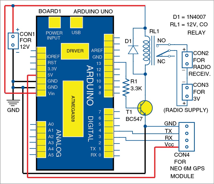
The GPS Timer For Your Radio Set system coordinates precise timing and automated power switching using an Arduino Uno as its central processing unit. At the heart of the timekeeping mechanism is the NEO-6M GPS module, which captures highly accurate Coordinated Universal Time (UTC) signals from overhead satellites via its external antenna. The Arduino communicates with this GPS receiver using the SoftwareSerial library to free up the hardware serial pins, while the TinyGPS++ library parses the incoming NMEA data strings to extract the exact hour, minute, and second. The system is programmed with a specific operational schedule. When the current GPS time matches a pre-configured target time, the Arduino alters the logic state of one of its digital output pins. Because the microcontroller's digital pins operate at 5V and cannot directly drive heavy loads or control the separate power rail required by the radio receiver, this control signal is routed to a BC547 NPN transistor configured as a digital switch. When the microcontroller applies a small base current to the BC547, it saturates and allows current to flow through the coil of the single-changeover relay (RL1). The energization of this electromagnetic relay mechanically actuates its contacts, acting as a switch to bridge or interrupt the circuit supplying the 3V DC power supply to the FM receiver. Powering the entire control circuit is a 12V 1A SMPS power supply, which delivers a stable DC voltage to the Arduino Uno and peripheral hardware. Through this integration of satellite data acquisition, software logic evaluation, transistor-transistor switching, and electromechanical relay control, the radio receiver is automatically toggled on and off without human intervention.
Why Build This
Automate the operation of vintage or standalone FM radio receivers to activate strictly during specific broadcast schedules like scheduled announcements or news programs.
Implement absolute time synchronization in remote or off-grid environments by leveraging satellite-derived UTC data rather than relying on drift-prone internal real-time clocks.
Master the integration of microcontroller digital logic with discrete switching components to safely control separate power domains.
Real-World Application
Automating radio receivers or appliances to turn on strictly at specific broadcast schedules, such as news programs or scheduled announcements.
Skills You'll Learn
GPS NMEA data parsing
asynchronous serial communication via software emulation
transistor-based load switching
electromechanical relay interfacing
power supply distribution
Safety Precautions
Ensure proper handling of AC/DC power loads when connecting the relay to avoid electrical shock.
Technology Tags
GPS
NEO-6M
ARDUINO
RELAY
RADIO
NMEA
TIMEKEEPING
AUTOMATION
Frequently Asked Questions
GPS signals rely on weak radio frequency transmissions from satellites in Earth orbit, which easily attenuate or get blocked by building structures. An external antenna helps maintain a reliable line-of-sight connection for accurate time locking.
No, microcontrollers have strict limits on the amount of current their output pins can source. Drawing too much current will damage the onboard voltage regulator or the microcontroller itself, which is why a dedicated 3V DC power supply routed through a relay is used.
The Arduino digital pin outputs a low-current signal that is insufficient to directly energize the electromagnetic coil inside the relay (RL1). The BC547 acts as a current amplifier, using the small microcontroller signal to safely switch the higher current required by the relay coil.
Gallery
This page is part of Kitkraft's Project Hub — a curated collection of electronics & robotics projects gathered from the maker community to help students and hobbyists discover and learn to build. Kitkraft does not claim authorship of the original project, and makes no representation as to the accuracy, completeness or safety of third-party source material. The summary and "How It Works" explanation above are AI-generated, rewritten with reference to the original tutorial — not a reproduction of it. Full credit and a direct link to the original source are provided above. If you're the original creator and have a concern about how your work is represented here, please contact us and we'll address it promptly.
 Arduino UNO R3 Board (Compatible) – ATmega328P Microcontroller with USB Cable
Rs. 999.00
 5V 1 Channel Relay Module
Rs. 87.00
 MB102 Adjustable Breadboard Power Supply Module (3.3V & 5V) for Arduino & Raspberry Pi
Rs. 139.00
 Jumper Wire 10 Pin Male To Male 20cm
Rs. 45.00
 400 Points Mini Solderless Prototype PCB Breadboard High Quality
Rs. 89.00
 Jumper Wire 10 Pin Male To Female 20cm
Rs. 45.00


